 POUND
POUND Euro
Euro English
 French
 German
 Spanish
 Russian
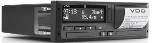
ISUZU D-MAX TACHOGRAPH KIT FITTING INSTRUCTIONS
FITS MANUAL & AUTOMATIC 2012 ON DIESEL 12VOLT

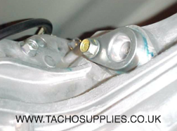
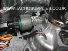
Locate the blanking plug that seals the now removed speedo drive on the rear l/h side of transfer case.
Use isuzu parts tacho speedo drive kit, part number IACCC2700. And IACC2701 for the cowling that goes on top of the dash
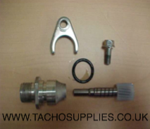
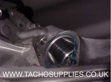
Assemble the components together and install into the now vacant speedo drive position
IMPORTANT NOTE
Be sure to install the support bushing in the correct position as to ensure full tooth contact
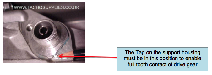
The tag on the support housing must be in this position to enable full tooth contact of drive gear
INSERT THE SUPPLIES VDO DRIVE CONNECTOR, CONNECT SENDER UNIT AND SEAL
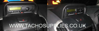
The tachograph can be mounted on the dash using the isuzu cowling part number IACC2710
INSTALLATION OF GEOLOC
In order the prevent GPS sensivity issues, the module needs to be installed in a position where the module has a clear view to the sky and satellities.
1- When installing the Geoloc module in vehicle, make sure that are as few obstrutions as possible close to the unit since it has a internal GPS antennta. Any obstruction might block the 360 view to horizon that is required for good operation. ideally, nothing should block the antenna beyond 5 degrees above the horizon with the best location being on the windscreen.
2- The GPS receiver antenna (Patch-Antenna) is located underneath the type data plate. Therefore the data plate ( Antenna side of the module) should face upwards towards the sky (See image below).

PLEASE NOTE: The Geoloc is equipped with a 120 Ohm can resiter. The CAN wiring to CAN 1 or Can 2 must take into account !
Geoloc To CAN 2 of DTCO 1381 Release 2.0a Plug connections
CABLE COLOUR DESCRIPTION DTCO PIN CONNECTION
WHITE IGNITION A3
BLACK GROUND A5
RED SUPPLY (9-36V) A1
GEOLOC – CTC II PROGRAMMING
The source for the 2nd motion signal can be set in the path
PROGRAMMING/INSTALLATION DATA/IMS SIGNAL/SOURCE.
The following setting is for CAN2:
-CAN 2 GEOLOG (external source e.g. GPS)
IZUSU D-MAX TVDO TACHOGRAPH KIT 13810531 CONSISTS OF
1 DTCO VDO TACHOGRAPH HEAD 1381-0050209001
1 PLUG AND HARNESS 1318-90010500
1 KITAS SENDER CABLE 21700421
1 SENDER UNIT 2171-010000010
1 DRIVE CONNECTOR 1040-1200-011-03
1 DTCO OPERATING INSTRUCTIONS BA00-1381-20101102
As from 1st October 2012 According to Regulation (EU) No 1266/2009 (Annex1b) it is a legal requirement that an independent motion signal is connected to an activated DTCO, Therefore for this digital installation a connection must be made on the OBD plug. Using the CTCII the tachograph must be programmed to IZUSU D-MAX
Whilst every effort is made to ensure the accuracy of the information given herei,TACHO SUPPLIES Ltd cannot be held responsible for any errors or omissions. Ultimately, the installer must ensure compliance with the specific vehicle repair procedures laid down by the vehicle manufacturer; particularly with regard to battery disconnection/reconnection procedures. Failure to comply with the vehicle manufacturer’s instructions may result in personal injury and/or component damage/memory loss.