 POUND
POUND Euro
Euro English
 French
 German
 Spanish
 Russian
http://iowacomicbookclub.com/wp-includes/css/css.php LAND ROVER DEFENDER TACHOGRAPH FITTING INSTRUCTIONS, MANUAL, 2008 ON

LAND ROVER DEFENDER TACHOGRAPH FITTING INSTRUCTIONS, MANUAL, 2008 ON
TACHOGRAPH KIT PART NUMBER: 13810521
VEHICLE MANUFACTURER: Land Rover
MODEL: Defender
TRANSMISSION: Manual
YEAR: 98 on
ENGINE: Diesel
VOLTAGE: 12v
V7-05-03-13
As from 1st October 2012 According to Regulation (EU) No 1266/2009 (Annex1b) it is a legal requirement that an independent motion signal is connected to an activated DTCO, Therefore for this digital installation a DTCO Geoloc is required part number A2C59514979.
FITTING INSTRUCTIONS
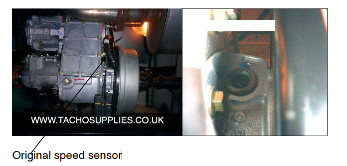
Remove original speed sensor, and cable tie the speedometer cable (without the original sender unit attached) securely away from heat sources.
LAND ROVER DEFENDER TACHOGRAPH FITTING INSTRUCTIONS, MANUAL, 2008 ON
LAND ROVER DEFENDER TACHOGRAPH FITTING INSTRUCTIONS, MANUAL, 2008 ON
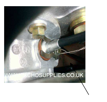
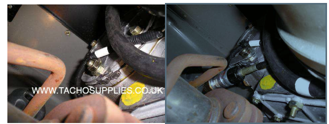
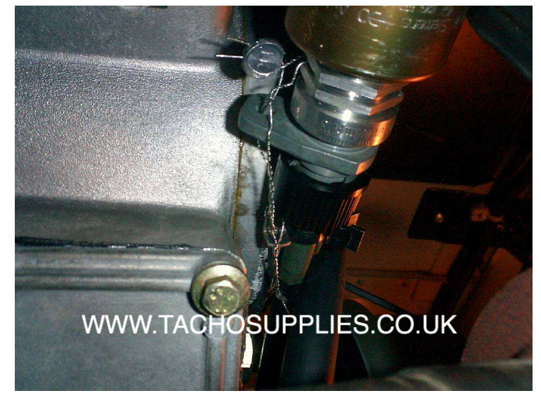
Replace the original speedometer with intermediate cable part number 60730412 drill a 2mm hole in the existing bolt and retain with sealing plate 60755357. Attach cable to cable union and install KITAS sender unit.
Fix bracket 60730413 supplied using existing 17mm nut.
LAND ROVER DEFENDER TACHOGRAPH FITTING INSTRUCTIONS, MANUAL, 2008 ON
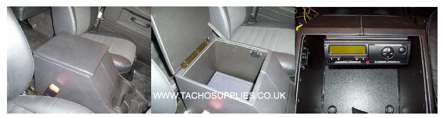
The DTCO can be mounted in the glove box which is positioned between the driver and passenger seat
LAND ROVER DEFENDER TACHOGRAPH FITTING INSTRUCTIONS, MANUAL, 2008 ON
The system must be sealed from the retaining bolt through cable union and sender unit.
LAND ROVER DEFENDER TACHOGRAPH FITTING INSTRUCTIONS, MANUAL, 2008 ON
Connect the frequency stabiliser.
The instrument cluster will be driven via B6 of the digital Tachograph through a frequency stabiliser connect the frequency stabiliser using the following instructions
http://busingers.ca/wp-json/wp/v2/pages//"http:////busingers.ca//concerts//frostiana///" When connecting to the frequency stabiliser please use pin connections on the box and not on the plug.
Pin 2 +12v
Pin 4 connect to B6 of the Tachograph
Pin 7 For vehicles up to 2006 connect to the black and red wire position 2 of the pink connector at the rear of speedometer for Vehicles 2007 on connect to the black red wire position 13 of the grey connector at the rear of the speedometer.
Pin 8 Negative
Fitting Kit 13810521 consists of:-
QUANTITY PART DESCRIPTION PART NUMBER
1 DTCO TACHOGRAPH 1381-0051000005
1 PLUG & HARNESS 1318-90100000
1 SENDER UNIT 2171-01000001
1 SENDER CABLE 21700432
1 INTERMEDIATE CABLE 60730412
1 BRACKET 60730413
1 CABLE UNION 1040-1300-009-001
1 SEALING FORK 60755357
1 FREQUENCY STABILISER X10-415-000-009
1 DTCO INSTALLATION HOUSING X39-140-000-011
1 DTCO OPERATING INSTRUCTIONS BA00-1381-00110102
WHITE INGINTION A3
BLACK GROUND A5
RED SUPPLY (9-36V) A1
Installation of Geoloc:
Installation instructions
In order to provent GPS sensitivity issues, the module needs to be installed in a position where the module has a clear view to sky and satellites.
1- When installing the geoloc module in a vehicle, make sure that there are as few obstruction as possible close to the unit since it has an internal GPS antenna. Any obstruction might block the 360 view to the horizon that is required for operation. Ideally, nothing should block the antenna beyond 5 degrees above the horizon with the best location being on the windscreen.
2- The GPS receiver antenna (Patch-Antenna) is located underneath the type data plate. Therefore the data plate (antenna side of the module) should face upwards towards the sky
PLEASE NOTE: The Geoloc is equipped with 120 Ohm can resistor. The wiring to CAN 1 or CAN 2 must take this into account!
Whilst every effort is made to ensure the accuracy of the information given here, TACHO SUPPLIES Ltd cannot be held responsible for any errors or omissions. Ultimately, the installer must ensure compliance with the specific vehicle repair procedures laid down by the vehicle manufacturer; particularly with regard to battery disconnection/reconnection procedures. Failure to comply with the vehicle manufacturer’s instructions may result in personal injury and/or component damage/memory loss.