 POUND
POUND Euro
Euro English
 French
 German
 Spanish
 Russian
Longfield IZUZU RODEO TACHOGRAPH FITTING INSTRUCTIONS, MANUAL & AUTOMATIC, 2006 ON

- IZUZU RODEO TACHOGRAPH FITTING INSTRUCTIONS, MANUAL & AUTOMATIC, 2006 ON

Rodeo
Manual and Automatic
2006 on
Manitowoc Diesel
12v
As from 1st October 2012 According to Regulation (EU) No 1266/2009 (Annex1b) it is a legal requirement that an independent motion signal is connected to an activated DTCO, Therefore for this digital installation a DTCO Geoloc is required part number A2C59514979.
FITTING INSTRUCTIONS
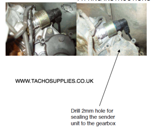
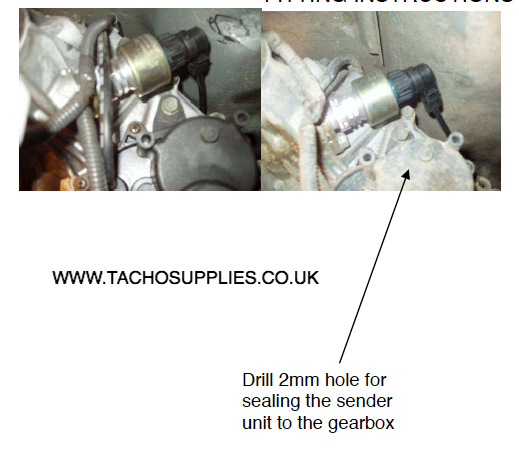
Remove original speed sensor and replace with 2171-01000010 using the 1040-1200-011-03 drive connector supplied, tape back the original sensor cable and install 21700432 KITAS sender cable.
- IZUZU RODEO TACHOGRAPH FITTING INSTRUCTIONS, MANUAL & AUTOMATIC, 2006 ON
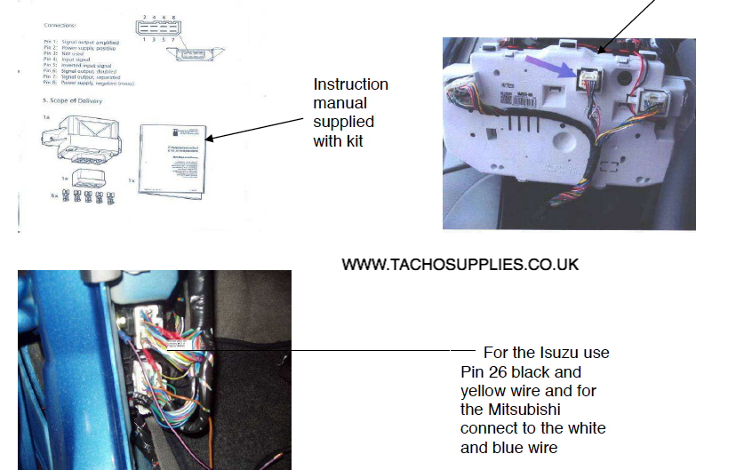
Connect the frequency stabiliser. The instrument cluster will be driven via B6 of the digital Tachograph through a frequency stabiliser connect the frequency stabiliser using the following instructions.
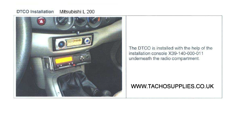
When connecting to the frequency stabiliser please use pin connections on the box and not on the plug. Pin 2 +12v Pin 4 connect to B6 of the Tachograph Pin 7 connect to the black and yellow wire found on the white plug at pin 26 and for the Mitsubishi connect to the white and blue wire on the passenger side foot well see picture below or behind the instrument panel, white 12 pin connector (middle one) position 2 white/blue. For the Kia Sorento connect to black/blue wire at the gearbox Pin 8 Negative.
Mitsubishi Instrument Panel

- Mitsubishi Instrument Panel

- IZUZU RODEO TACHOGRAPH FITTING INSTRUCTIONS, MANUAL & AUTOMATIC, 2006 ON
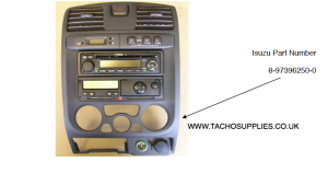
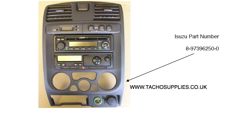
The DTCO can be installed using the double din panel that can be obtained from Isuzu
- IZUZU RODEO TACHOGRAPH FITTING INSTRUCTIONS, MANUAL & AUTOMATIC, 2006 ON

- IZUZU RODEO TACHOGRAPH FITTING INSTRUCTIONS, MANUAL & AUTOMATIC, 2006 ON
WHITE INGINTION A3
BLACK GROUND A5
RED SUPPLY (9-36V) A1
Fitting Kit 13810513 consists of:-
QUANTITY PART DESCRIPTION PART NUMBER
1 DTCO TACHOGRAPH 1381-0050209001
1 PLUG & HARNESS 1318-90100000
1 SENDER UNIT 2171-01000010
1 SENDER CABLE 21700432
1 DRIVE CONNECTOR 1040-1200-011-03
1 FREQUENCY STABILISER X10.415/000/009
1 DTCO MOUNTING SLEEVE 1324-90010500
1 DTCO REAR SEALING COVER 1381-90020100
1 DTCO REAR SEALING COVER SCREW HS07-0100-116
1 DTCO OPERATING INSTRUCTIONS BA00-1381-20101102
Installation of Geoloc:
Installation instructions
In order to provent GPS sensitivity issues, the module needs to be installed in a position where the module has a clear view to sky and satellites.
1- When installing the geoloc module in a vehicle, make sure that there are as few obstruction as possible close to the unit since it has an internal GPS antenna. Any obstruction might block the 360 view to the horizon that is required for operation. Ideally, nothing should block the antenna beyond 5 degrees above the horizon with the best location being on the windscreen.
2- The GPS receiver antenna (Patch-Antenna) is located underneath the type data plate. Therefore the data plate (antenna side of the module) should face upwards towards the sky
PLEASE NOTE: The Geoloc is equipped with 120 Ohm can resistor. The wiring to CAN 1 or CAN 2 must take this into account!
Whilst every effort is made to ensure the accuracy of the information given here, TACHO SUPPLIES Ltd cannot be held responsible for any errors or omissions. Ultimately, the installer must ensure compliance with the specific vehicle repair procedures laid down by the vehicle manufacturer; particularly with regard to battery disconnection/reconnection procedures. Failure to comply with the vehicle manufacturer’s instructions may result in personal injury and/or component damage/memory loss.